Written by Rudi Botha, Process Engineer & Robert Kovacs, Technical Expert – Engineering
Pt 3. Reactor sizing in a MBBR Plant
In Part 1 of this blog series, the Transcend Design Generator (TDG) is introduced as a software-as-a-service (SaaS) platform helping you generate preliminary designs for wastewater treatment plants. It is available at transcendh2o.com, after a free registration.
MBBR is also defined in Part 1 as the Moving Bed Biofilm Reactor technology. The data required to start an MBBR design is described, and Part 2 discusses the process arrangements available in the TDG.
In this third part of the series, we will look at the process design that determines the reactor sizing in the TDG.
What is MBBR reactor sizing based on?
The unique characteristic of MBBR technology is the retention of the biomass on the suspended media in the reactor. This biofilm that grows on the media is home to the active organisms that consume the excess nutrient load in the influent. An increase in media surface area allows more space for biofilm growth; however, large volumes of media require additional mixing to ensure that the influent meets the biofilm for adequate treatment. Therefore, the design is based on the optimal media/carrier surface area, shape and density that can be provided to achieve biofilm growth.
Surface area removal rate (SARR)
The surface area removal rate (SARR) is the key design parameter used to size an MBBR reactor. SARR is the rate of nutrient removal for every unit of carrier surface area. The values and ranges have been determined empirically for different reactor conditions. For example, in BOD removal aerobic reactors, the SARR ranges from 5 to 15 gBOD/m2/d for domestic wastewaters (Metcalf & Eddy, 2014), i.e. for every square meter of surface area provided by the carrier, the influent load can be reduced by 10 gBOD/d on average.
Surface area loading rate (SALR)
The surface area loading rate (SALR) is often referred to as the key design parameter of MBBRs, but it can be derived from SARR through application of the treatment efficiency. Typical treatment efficiency in a BOD removal aerobic reactor treating domestic wastewater is 75% (Metcalf & Eddy, 2014). The treatment efficiency is dependent on many factors including water temperature, shape and density of the carrier, mixing and dissolved oxygen (DO) in the reactor, shape of the reactor, etc. Hence, it is important to adjust the treatment efficiency according to these factors if they are outside of the standard ranges assumed when determining the typical treatment efficiency in reactors. When using SALR as a design parameter, the treatment efficiency is hidden behind the calculation of SALR, and not carefully considered in the design. This is why SARR is a better design parameter for the MBBR reactor.
Carrier surface area and volume
From the SALR and influent nutrient loading, the required carrier surface area required in the MBBR reactor can be determined. Carrier media suppliers list the carrier specific surface area (m2/m3) and carrier void space fraction, which can be used with a design reactor fill fraction to determine the carrier volume and reactor volume required for the design.
Biofilm thickness
These empirical calculations described thus far provide a basic design estimate for the sizing of an MBBR reactor, and a starting point for a dynamic simulation. However, empirical designs assume standard conditions to determine the treatment efficiency and SARR factors. To ensure that the assumptions thus far have produced a design that is conducive to your specific influent fractionation and site conditions, a dynamic simulation can be used with fundamental parameters such as biofilm growth factors. These factors include
- Surface area biofilm growth rate
- Biomass fraction of biofilm
- Biomass density
- Biofilm thickness, which varies with reactor conditions
- Diffusion boundary layer thickness
- Attachment velocity of flocs to biofilm
What data does the TDG need to size the reactor?
Input data required
There are no compulsory input process design parameters in the TDG for MBBR and IFAS. However, the parameters indicated in the figure below, and their typical values, can be adjusted according to your project specific needs. The following sections will take a closer look at these parameters and what they are used for in the TDG.
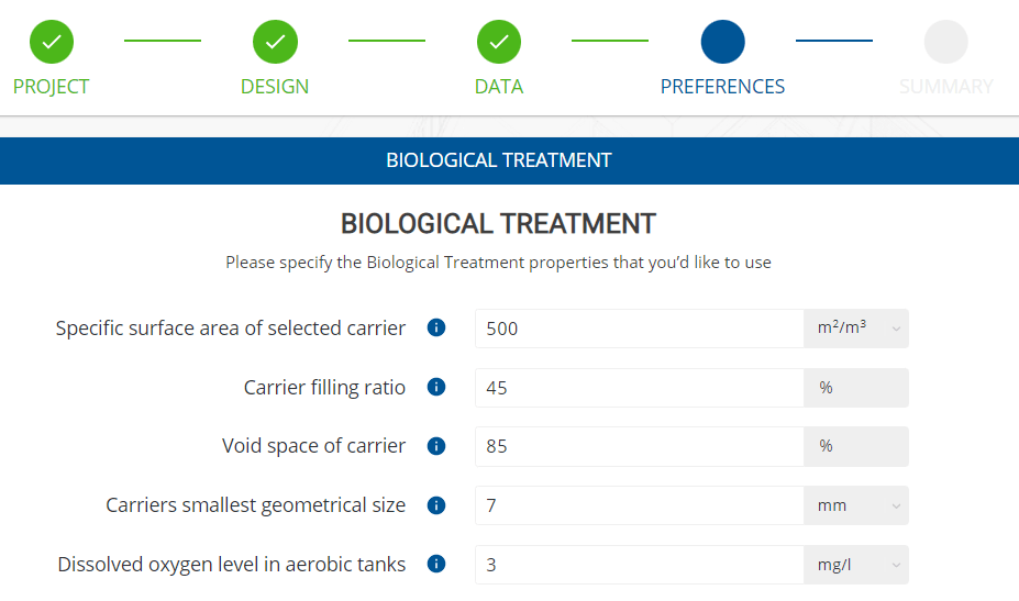
Specific surface area of selected carrier
The carrier specific surface area is the surface area per unit of carrier total/bulk volume. This total volume, which includes the void space of the carrier, would be the volume required in the truck that will deliver the carrier media.
This parameter is used, along with the total carrier surface area required to remove the influent nutrient loads and the carrier filling ratio, to determine the reactor volume required.
It is a parameter that is listed by suppliers of carrier media in their product specification sheet. But be careful when selecting a carrier media as a higher specific surface area, i.e., more surface area for the same total volume of carrier, does not always mean more treatment efficiency. At very high specific surface areas there is limited space between surfaces in the media for biofilm to grow and be exposed to oxygen, reducing the treatment efficiency. To ensure that the design efficiency is not compromised by the geometry of the carrier in this way, the TDG allows a value range of 200 to 780 m2/m3 for this parameter.
Carrier filling ratio
The carrier filling is the ratio of the total volume of the carrier to the total volume of the reactor. This will be the fraction of the reactor that is filled by the carrier when delivered into the empty reactor during commissioning. As mentioned above, it is used alongside the carrier specific surface area to determine the reactor volume required.
This value will also be influenced by the geometry and material properties of the carrier. For example, for heavier materials, a lower filling ratio would be more appropriate to ensure that the mixing or aeration is able to keep the carrier suspended in the reactor.
Void space of carrier
The void space is the fraction of the total volume of the carrier that is air. Since the media is designed to have a high surface area, there are many gaps that biofilm can grow in and a large portion of the total volume of media is hollow. This empty space relative to the total volume of the carrier is the void space.
When the void space is used with the total carrier volume, the net volume of the carrier, which is the solid part, can be calculated. The volume of the solid part of the carrier is important as it displaces some of the total reactor volume. This reduces the volume of influent flow that the reactor can hold, or the reactor’s hydraulic retention time (HRT). The HRT is the time that the influent flow will come into contact with the biofilm and undergo treatment for nutrient removal. Therefore, the void space plays a critical role in the design of the reactor.
Smallest geometrical size of carrier
The smallest geometric size is the smallest dimension of one carrier’s total length, width or height. This parameter is used to size the screens at the end of an MBBR reactor that retain the carriers, preventing them from being washed out of the reactor with the effluent flow. The geometry of a carrier is also specified by the supplier.
Dissolved oxygen level in aerobic tanks
The dissolved oxygen level in an aerobic tank is a parameter used to control the speed at which the biofilm grows, as organism growth requires oxygen. However, adding more oxygen to an aerobic zone also increases the mixing and turbulence, which breaks biofilm off the carrier, and it exists the reactor with the effluent. Therefore, a balance of too much and too little aeration is required.
Some carriers might be geometrically designed for higher turbulence and others for lower turbulence; therefore, this parameter can be set according to the carrier or user specific needs.
How does TDG automate the reactor sizing?
Initial sizing
The empirical calculation method described above is used for an initial estimation for reactor volume based on design guides from Metcalf & Eddy et al. (2014), Ødegaard (2006) and McQarrie & Boltz (2011). This provides the steady state and dynamic simulations with reactor volumes, internal recycle rate, carrier surface area and geometry.
Reactor sizing optimization
The initial sizing is used as a starting point in a series of steady state simulations, followed by an annual dynamic simulation. Between simulations, the TDG checks the effluent limits and design parameters required and adjusts the design to meet these criteria. For the inner workings of these simulations and the reactor sizing optimization logic of the TDG, have a look at this blog post that dives into the details.
How are the TDG designs presented?
The TDG produces a full set of editable preliminary design documents and drawings, from a technical description of the process design to civil BIM models, mechanical equipment lists, and an opex summary, inter alia. In the next part of this blog series, we will go behind the scenes on how these output documents are automatically generated by the TDG.
References
Metcalf & Eddy Inc., Tchobanoglous, G., Burton, F. L., Tsuchihashi, R., & Stensel, H. D. (2014). Wastewater engineering: Treatment and resource recovery (5th ed.). McGraw-Hill Professional.
Ødegaard, H. (2006). Innovations in wastewater treatment: –the moving bed biofilm process. Water Science Technology 1 May 2006; 53 (9): 17–33.
Mcquarrie, J.P., & Boltz, J.P. (2011). Moving Bed Biofilm Reactor Technology: Process Applications, Design, and Performance. Water Environment Research, 83.